You should find the following in your kit:
- 3 Wire Harnesses with 4 Switches
- 1 Baggy of miscellaneous Terrific stuff
- These Instructions; PA24 thru s/n 2201
- Your Receipt
Preface and Commentary
First allow me to thank you for purchasing this product; I take pride in its quality and completeness. Also I thank the installer for taking the time to read and understand this manual which will benefit the installation with multiple time savings. Use your Comanche Gear high-light pen to mark any areas you like for reference which will also make this effort easier for you. I have performed many installations and maintain the effort to keep these various manuals updated for clarification, a better method, a timesaver hint, and from your feedback. They are periodically quite a time-consuming project to update but necessary and I apologize for the appearance of a lengthy manuscript; it is for your advantage. The feedback is appreciated from those many happy customers; don’t hesitate to participate as it can only help improve the product line.
Your wire harness assemblies complete with switches are made similar to the original factory product with the following exceptions. #1) the wire used is current mil-spec MS22759 [Tefzel® insulated] as stated in AC43.13-1B – see page 33. #2) the sleeve is silicone-coated fiberglass rated at 200°C instead of the original PVC sleeve which is rated at 80°C to 105°C. The original PVC sleeve when new is clear and very flexible; both of these qualities deteriorate with age and/or elevated temperature. The sleeve used in your harness will maintain its flexibility over time and survive the proximity of the exhaust system’s heat. #3) the wires G14A & G15A previously co-located at the safety switch are now terminated together in a knife terminal at the wing root end of the harness, no change electrically, a physical change for manufacturing only. And like the originals each wire has its circuit element marked into the insulation, watch for these marks as they are key to a successful installation. The marks are imprinted onto the insulation using the hot-stamping process with Kingsley® equipment just like Piper used. There are
limitations to marking on Teflon®; they don’t like to stick so handle the wires carefully.
Right Main Gear
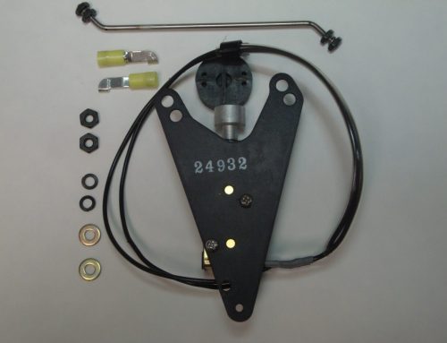
Starting with the right side harness is the simplest and will get the ball rolling and your learning curve will be best utilized. Don’t fret; you do not have to remove the flooring for access to the wiring. Place the airplane on jacks as outlined in the Comanche service manual section 2-11; and do not fail to tie the tail to an adequate weight – 400-lbs so says the service manual. Pull the “gear motor” circuit breaker knob and don’t forget to reset it upon completion. Disconnect the gear transmission – see page 4 – manually retract the gear a bit and then block the extended lever against the lower instrument panel section or under the nose wheel with a piece of 2“ x 4“ – see page 5. Remove the cotter pin, castle nut, washer, and screw at the side-brace stud where the harness clamp is located and separate the drag link from the side-brace stud [don’t lose the bushing], this will allow you to break the knee action which will make the adjustment of the main gear limit switches easier; the switch action is audible. Remove the lower aft wing-root fairing to expose the harness connectors. Cut the old harness inside the wing area – photo page 6 – where the wire marks are still legible, this may save some time and grief while connecting the new wires to the old, especially if the aircraft has been painted. Pull the harness out of the wing and remove the insulation over the knife terminals [pointed-blade Exacto® knife works well] but do not disconnect the knife terminals yet. Remove the cushioned clamp hardware and cable ties, and then pull the switch-end section of harness out of the wing. Remove the old grommets in the wing ribs using a pointed-blade Exacto® knife. At the switch end remove the retaining nut with the boot for the micro switch actuator at its mounting bracket. Remove the harness assembly with the switch and actuator attached and save for reference, it will show you where the clamps were positioned so leave them on the harness for that reason. Lay all that stuff on a bench and be careful when removing the switch from the actuator because the actuator plungers and spring can fall out and potentially be lost.
Contact Comanche Gear
Please provide your complete details for invoicing such as your Card Billing Address, Shipping Address, and Aircraft Information. If you want to gab on the phone don’t hesitate to call, especially if you want to order something. If you have a problem-solving dilemma I can help with that too. This website doesn’t have internet ordering capabilities; that is for those more sophisticated. My email isn’t shown here because of scam artists and other shenanigans.