Mark components before disassembly; Use CR3213-5-5 rivets to reinstall the collar.
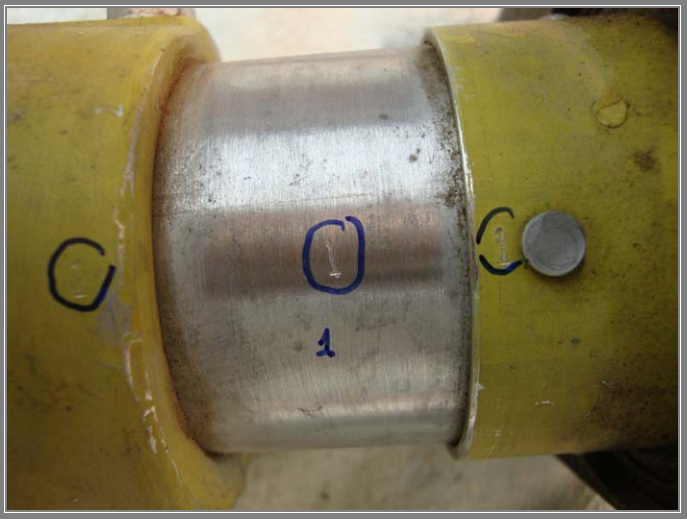
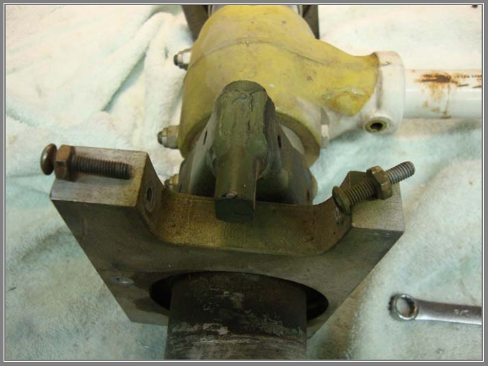
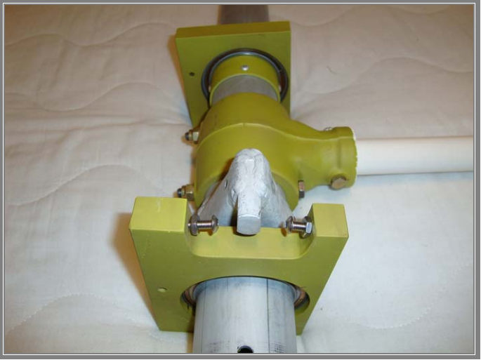
Note orientation of the bearing blocks; this hole is for the trim
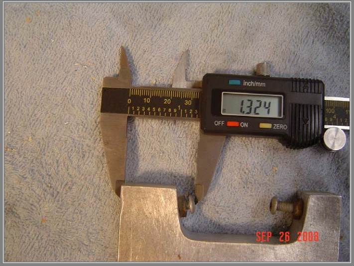
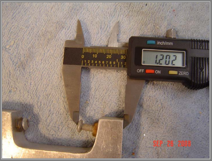
Measure the limit stop settings before disassembly [400 shown here]; this makes a good place to start the limit adjustment procedure. New stainless steel stop screws and locknuts are supplied; see the photos below.
A “Before” Photo
An “After” Photo
Do not paint the torque tube; doing so would make subsequent disassembly difficult should that be required per AD or other.
Piper Service Bulletin number 1160 specifies two corrosion inhibitor products for “all other reworked items”, whatever that means. It does not specify a product for the torque tube other than “2 swab coats of epoxy primer” to the interior. After the epoxy primer I suggest applying one of those specified or CorrosionX® [red can for steel components, blue can for aluminum] heavily to the inside of the torque tube before installation and lightly to the outside of the torque tube before further assembly [of the stabilators].
SB-1160 further states in part 2, 1; “… repair per chapter 6 of FAA document AC43 13-1B …”. Section 6 is corrosion removal [6-116] and plating [6-164].

I would also suggest further disassembly to check for cracking of the horn [future AD] and write the log book entry in hopes this work, if performed prior to the AD, will CYA. I also perform the unapproved procedure of chamfer and polish the bores’ intersection, plus dye penetrate or eddy current inspect, glass bead blast, clean, Alodine® and epoxy prime the aluminum components. I use an external stamped mark [a circled “M”] to indicate the procedure; see the photos elsewhere.
The aluminum components of the torque tube assembly as well as the inside of the torque tube have been painted using Sherwin Williams® Aerospace Coating Epoxy Primer MIL-P-23377F after proper preparation as mentioned above. The exterior of the balance tube and weight have been likewise painted using the MIL-P and Sherwin Williams® Acry Glo® white. You’ll notice there is minimal paint film thickness on the bearing blocks; an important detail. Paint-film thickness can be a source of fretting corrosion where the blocks attach to the aft bulkhead. If you choose to refinish the bulkhead please be aware of this detail; use only a thin coat of epoxy primer. Reference AC 43.13.1B, see section 6-22, fretting corrosion.
For another interesting read, go to AC 43.13.1B, see section 6-20. Therein is described one suggested [partial] failure mechanism for the cracking issue, stress corrosion cracking.
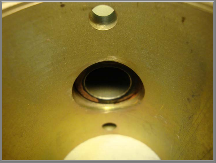
Note Sharp Edge at Bores’ Intersection!
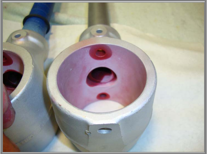
Chamfered and Polished Bores’ Intersection; Alodine(R) Treated.
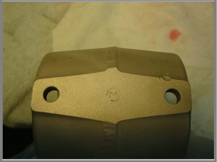
The circled “M” is my identification mark for processes mentioned
The visible penetrant test process
Contact Comanche Gear
Please provide your complete details for invoicing such as your Card Billing Address, Shipping Address, and Aircraft Information. If you want to gab on the phone don’t hesitate to call, especially if you want to order something. If you have a problem-solving dilemma I can help with that too. This website doesn’t have internet ordering capabilities; that is for those more sophisticated. My email isn’t shown here because of scam artists and other shenanigans.