Diagnostic Procedure for Single Comanche Fuel Quantity Indicator Selector Switches
If you are experiencing erroneous fuel quantity indications in your Comanche this may be of some interest and assistance in the diagnosis and repair of the fuel quantity indicating system. This is not intended to replace the methods found in any service manuals nor to re-hash them; rather to offer additional information. And obviously one should refer procedurally to the appropriate manual. You determine if your capabilities include doing this yourself; there isn’t much mystery involved once the system is understood. Reference: SCSM beginning paragraph 11–78; included below.
An error in fuel quantity indication can be caused by an incorrect resistance value being transmitted to the display gauge unit. There can be a few sources for this problem. Checking for poor connections should be your first line of diagnosis, secondary would be a component. If you have focused your search on the fuel valve selector area, this article will lend some assistance and suggestions in that area.
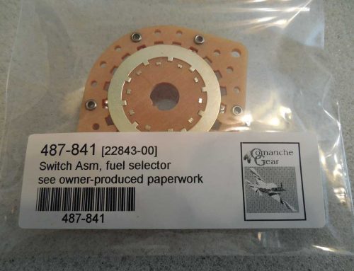
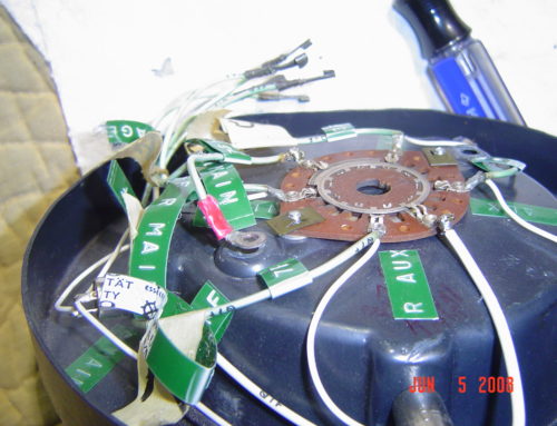
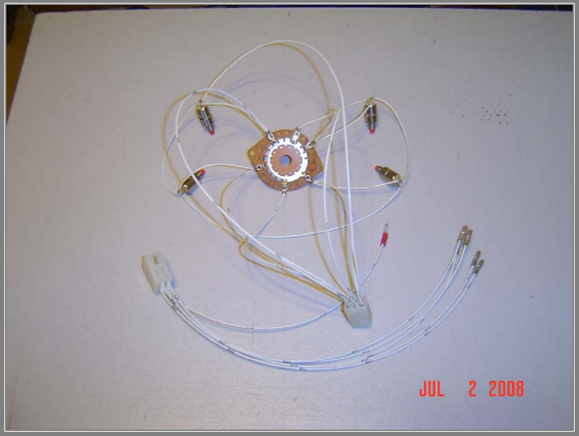
On the single models with one fuel gauge display unit you will find 4 over–ride red push-button switches and a selector switch co-located with the fuel tank selector. This area is usually accessed during the annual inspection and potentially subject to repeated handling which can cause a broken connection or other malady. Another problem in this area, one or more of these electrical components may have developed some resistance which will add to the value from the fuel level transmitter, the result will be erroneous fuel quantity indication. So if you have this type system let’s put this on the diagnostic check list in addition to the gauge, fuel transmitters, and connections.
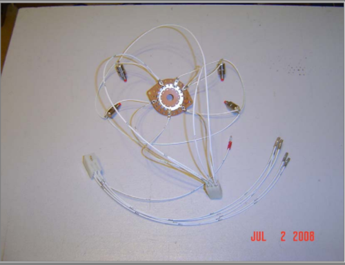
Now let’s move on to the work-related portion. Remove the subject fuel selector protector plate as an assembly. Also look carefully here for a problem with the knife terminals or a soldered connection. Examine the solder terminals at each over–ride switch, these may have been disturbed and possibly touching each other or broken. Note the knife terminal connections wrt each other; see the wiring diagram to follow. I think one excellent change is to put these 6 wires into a receptacle/plug housing assembly which will save time and assure correct connection each time this item is removed. Using an ohmmeter proceed to check one over–ride switch for continuity and resistance in each of its 2 operating positions, 1) from “C” to “NC” and 2) from “C” to “NO” with the button depressed. If the result is anything but zero–resistance in each instance you have found a problem. And likewise check the three remaining over–ride switches.
The wafer switch should also be checked for continuity, resistance, and mechanical function. The over–ride switches are not expensive unlike the wafer switch which is terribly so. It is possible to “repair” the hole in the wafer switch so it will again “key” properly to the shaft.

Typical Wiring Diagram Supplied with the Installation Manual
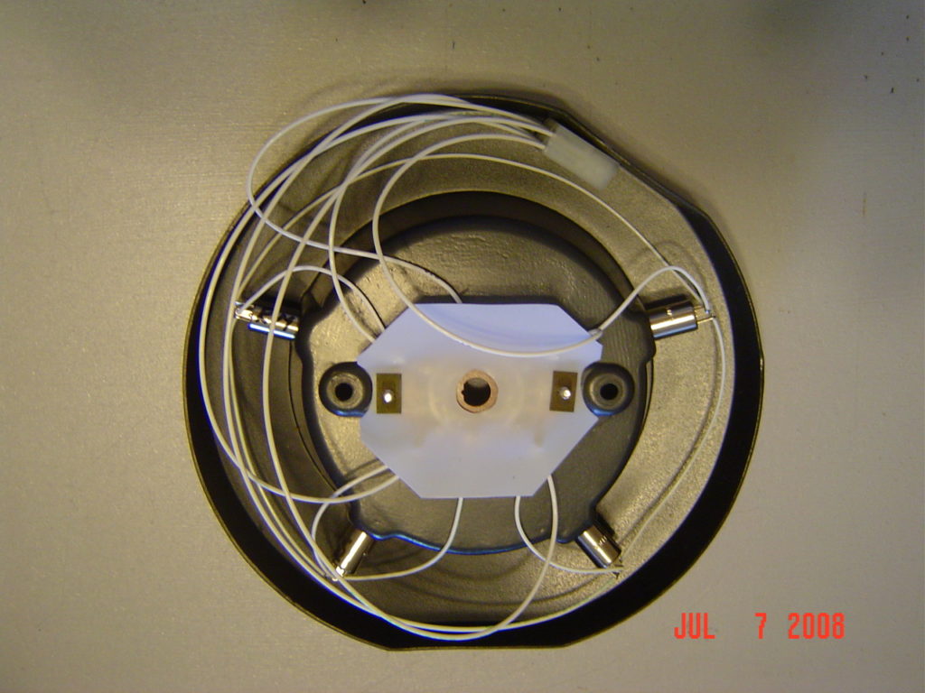
Fuel Selector Switches Assembled into Protector Plate
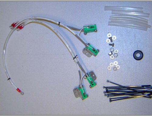
New Fuel Selector Switch Assembly