Suppose the engineers at Piper needed a method to determine whether the load on the landing gear transmission and motor was within the design criteria plus a safety factor. How would I do that? In the design phase of the retraction system a transmission method was selected and designed. In order to check that no
abnormal forces were overloading the transmission assembly, they came up with a simple force/load test, we refer to it as the landing gear retraction torque test.
How did they determine a load value, well that was easy [for an engineer]. The loadfactor value represents the sum of the parts plus that safety factor. The weight of each landing gear in its retracted position exerts a force on the conduit that can be simply determined [they did this in the design phase]; it’s a force diagram, levers and moments. Here’s the over-simplification. Let’s take all the landing-gear represented weights and put them on a teeter-totter. Now we’ll need to balance those combined weights. Your three children each weight 50 lbs and you weight 150 lbs; you are balanced on an equal-fulcrum TT. Suppose you curiosity was in overdrive after too much coffee and you wanted a measurement device to see what your kids combined weight was. At the fulcrum you would measure the torque applied by that combined weight. If the TT was 10 ft total, then at 5 feet times 150 lbs you have 750 ft-lbs of torque. If you wife at 135 lbs got on the TT the kids would not be happy. Ah, but she brought a cheater board with her. How long was it; one foot. 750 ft-lbs divided by 125 lbs equals 6 feet. The TT was 5 feet. Simple. The longer the effective arm, the less weight required.
Well that was easy to calculate, however to measure that in the airplane a method was chosen to simply the process. And the torque wrench and adapter method was chosen, since it’s easier than applying weights to a TT inside the airplane. See, it really is simple.
If the combined weights of the landing gear components exerted a force of 150 lbs on the TT, then a force valve seen on a torque-measuring device can be determined. That allowable value is given in the Piper Comanche Service Manuals. Whatever the length.
A torque wrench is a simple device, say you need 35 ft-lbs for your spark plug, dial in it and click [only one click is required by the way, unlike many mechanics’ methodology]. What if you had a special tool requirement? Well go to any chart or figure it out yourself. If the adapter adds effective length to the lever arm, then a lower force will be required to yield the specified torque valve. The longer the lever, the lower the force.
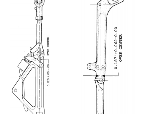
So then why does Piper specify increasing torque values for the longer effective arms? Hummm, another apparent mystery??? We aren’t changing the length of the extension, it is a design value. However we are changing the effective length of the torque wrench; that seems to be a reversal of the thinking process [or are we confused? If so then how then do we really know if our landing gear conduits are causing a problem [load] over the design criteria?
The answer is in the discussion, “effective length” which is also included in this seminar handout; see the next article.
The best type torque wrench to use is a recording type dial meter. Balance beam torque wrenches are yesterday’s news – remember it’s a 1956 design era.
See my article on Effective Length Landing Gear Retraction Loads
Contact Comanche Gear
Please provide your complete details for invoicing such as your Card Billing Address, Shipping Address, and Aircraft Information. If you want to gab on the phone don’t hesitate to call, especially if you want to order something. If you have a problem-solving dilemma I can help with that too. This website doesn’t have internet ordering capabilities; that is for those more sophisticated. My email isn’t shown here because of scam artists and other shenanigans.