This article is included with each baffle order as a bound booklet.
Hole Location for the Prop Governor Control
250 AND 260 ONLY
For the left side 21139-xxx you will need to determine the location of the hole required for the control rod preferably before you remove the old baffle or prop governor control rod, but this method will work either way with some adaptation. Place two pieces of masking tape at the approximate hole location cross-wise on the old baffle, one oriented on the longitudinal axis and one on the lateral axis. Measure from the crankcase to the centerline of the control rod and mark that lateral location on the tape and dimension in a note and drawing for your sanity. Likewise for the longitudinal dimension which is the distance from a tangent at the cylinder fins. Use a carpenter’s square or other ninety-degree fixture and call the tangent a line 90 degrees to the crank centerline. Measure from here to the centerline of the control rod and mark that longitudinal location on the tape and denote. Also you need you to consider the range of motion the control rod scribes through its travel. Note the lateral differential making this a factor in the hole’s location and size required. I hope this isn’t too cumbersome but it will give you the neatest job of locating the hole.
INSTALLATION – PLEASE READ THIS
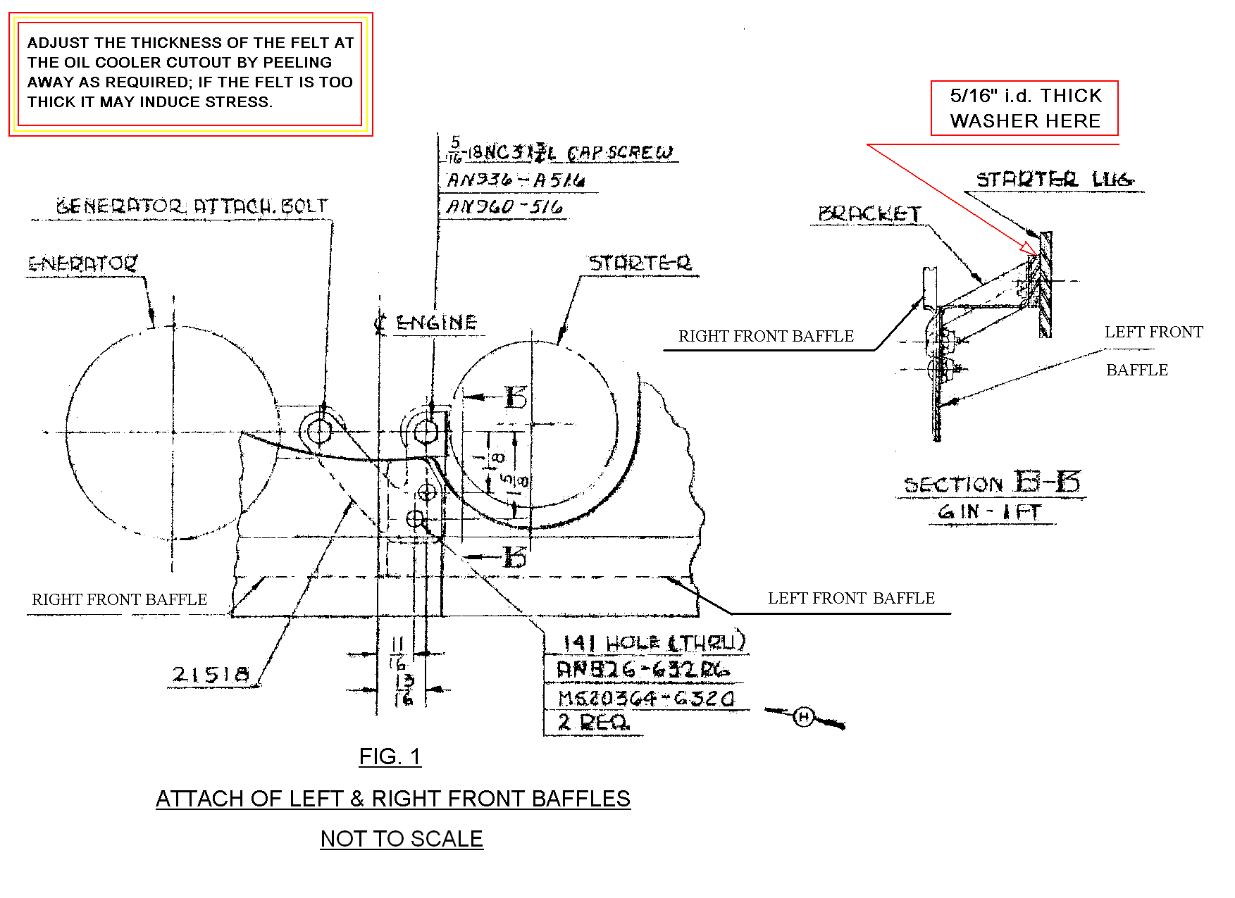
Position the baffles in place as accurately as possible; you will have some adjusting to do so don’t panic yet. For the left side baffle if yours has a small bump-out this has been located where a case screw/bolt head may interfere without it. The cooler cutout is the location key for this left baffle. Insert a screw with a large o.d. washer through the hole in the left baffle into the #2 cylinder head but don’t tighten it yet. You are considering four issues. 1) – the joining of the two baffles at the “bracket” [see included drawing]. 2) – The felt thickness at the cooler cutout. Adjust the thickness of the felt by peeling to it make thinner if required. If the felt is too thick it may induce stress [= crack, = bad]. 3) – The left side attachment to the adjoining #2 cylinder side baffle. 4) – The tension applied from the tightened tie rod between the fore and aft baffles. At some convenient point you will want to transfer the previously-determined dimensions for the location of the governor rod hole to the repaired baffle, making sure of the baffle’s fitment before doing so.
For the right side baffle note that you will likewise need to adjust to fit considering four issues. 1) – The joining of the two baffles at the “bracket” [see included drawing]. 2) – Proper alignments to avoid contact with the alternator / generator belt tension bracket. 3) – The right side attachment to the adjoining #1 cylinder side baffle. 4) – The tension applied from the tightened tie rod between the fore and aft baffles. The flywheel ring gear has been accounted for and should not present a clearance problem; take another look if you have this condition and reposition.
For the detail of the “bracket” see the included Piper assembly drawing where you may be able to make out what hardware should be used, note in the drawing the left side baffle is touching the bracket. Also note the spacer [extra-thick 5/16” large o.d. washer] that should be used and located between the “bracket” and the starter.
To locate the holes at this “bracket” use a #6 hole duplicator to drill the holes through the baffles at two screw locations, think twice, drill once; think ahead and pay careful attention to detail and you will be rewarded with a good-fitting installation.
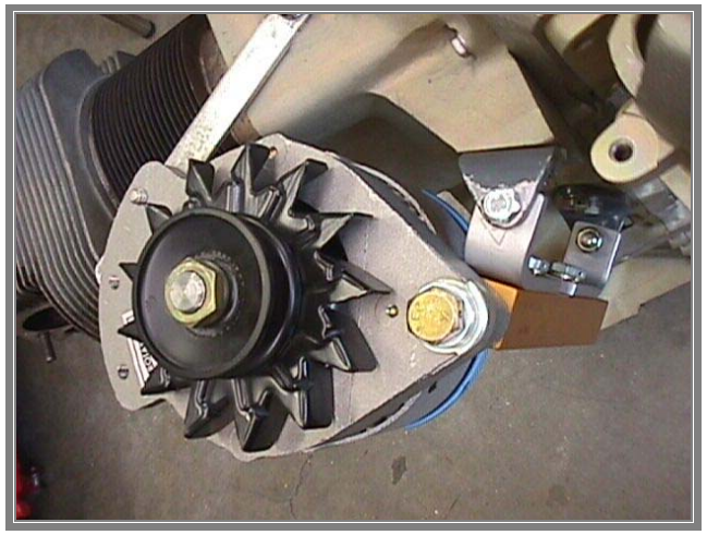
RIGHT SIDE BAFFLE WITH INTERAV ALTERNATOR KIT
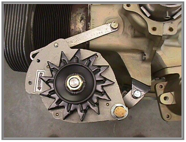
In order to avoid trimming the right side 21138-XX baffle you will have to configure the mounting brackets as pictured. The object is to keep the belt tension bracket with the slot for belt tension adjustment as low as possible so as to avoid contact with the baffle. The more this bracket approaches the horizontal the closer it is to the baffle, not good.
Contact Comanche Gear
Please provide your complete details for invoicing such as your Card Billing Address, Shipping Address, and Aircraft Information. If you want to gab on the phone don’t hesitate to call, especially if you want to order something. If you have a problem-solving dilemma I can help with that too. This website doesn’t have internet ordering capabilities; that is for those more sophisticated. My email isn’t shown here because of scam artists and other shenanigans.